                |
Principles of Engineering Controls for
Silica Dust
Engineering controls for silica refer to methods that can help to reduce the risk of
employee exposure to excessive amounts of silica dust. The engineering controls described here are:
In
addition to designing and installing engineering controls, inspection
and maintenance procedures should be scheduled regularly to help ensure their
continued effectiveness. Successful implementation and reduction of
employee respirable silica exposures below the PEL (preferably the
ACGIH TLV and OSHA Action Level) can negate the need for respiratory
protection and continual medical management required by the Silica Standards. This section provides an overview of some of the principles that apply when developing engineering control solutions for silica dust. Included are some of the advantages and disadvantages of each method. This section does not provide design procedures or guidance. Engineering professionals specializing in dust control should be consulted for further assistance. Introduction Replacing
silica-containing materials with silica-free substitutes is one
engineering control method to consider to help reduce the risk of
employee exposures to respirable silica. Selecting substitutes that
contain lower percentages of silica than the product currently used,
can help reduce exposures to airborne silica. Other products may have
varying percentages of silica in their filler materials and substitutes
with less hazardous fillers may be available. Any higher costs of
alternative products may be offset by reduced medical and disability
costs associated with any worker developing silicosis. Abrasive blasting operations using sand can present some of the highest exposures to airborne silica. Sand contains high percentages of crystalline silica and often comprises some or all of the components of abrasive blasting media. A variety of materials (i.e., corundum, glass beads, pumice, sawdust, slags, steel grit and shot, and walnut shells) are available as alternative materials and information about each is listed in the OSHA silica advisor - Silica Substitutes. Current recommendations from NIOSH and regulatory agencies in other countries prohibit the use of silica sand or materials containing greater than one percent crystalline silica for abrasive blasting. When selecting abrasive blasting alternatives, Safety Data Sheets should be consulted. Some silica substitutes, such as slags and grits, may contain toxic metals. If used, air monitoring should be conducted to determine if engineering controls or personal protective equipment should be used with these abrasives to help protect employees from additional hazards. Regardless of the abrasive media, the hazards from the materials removed (i.e. , lead-containing paint) pose health risks to the blasters.
When reviewing Silica Substitutes, note that the cost per ton can be misleading
when compared to silica sand because many substitutes can
be recycled. Cost per square foot may be a more useful index
of actual cost. The real cost will vary depending on the particular
application and factors associated with each job. Introduction
Hazardous substances can be isolated to help prevent contact
with workers. Isolation that reduces exposures and/or the
number of workers exposed may be achieved with a physical
barrier (full or partial enclosure of machines, processes
or people), distance, or time. Enclosures
Enclosures, combined with local exhaust ventilation, may be one
of the best methods available aimed at the control of hazardous
air contaminants, such as crystalline silica. An entire process,
part of a process, or specific sources can be enclosed to prevent
the escape of contaminants into the work area. Enclosed areas
for machines and processes should be kept under negative pressure
to help reduce fugitive emissions from the enclosure. Enclosures
can lower the exhaust requirements of a dust-collecting system
or help an existing dust-collection system work more efficiently.
Processes or operations that need to be completely enclosed
may be mechanized or automated and performed through remote
control or may be handled by means of gloved inlets. If partial or full enclosures are considered, pay attention to the following:
Whenever
full enclosures are not feasible, partial enclosures may be an option.
The approach to designing partial enclosures includes starting with a
full enclosure design and then removing the minimum possible that will
still permit performance of the operation. Partial enclosures may be
effective in combination with local exhaust ventilation systems, since
the partial enclosure may constitute the hood for the exhaust system.
Inspection
and maintenance of engineering controls should be scheduled regularly
to help ensure their continued effectiveness. Periodic worker exposure
air monitoring is one method to help determine the effectiveness of
enclosures. Regulated Areas
Entry to areas where crystalline silica exposures exist can
be restricted to a few workers who are included in the Silica
Control Program, for whom adequate respiratory protection
and medical surveillance are provided. Regulated areas should
be marked with warning signs at entrances and within the areas
to identify the controlled area, restrict access, identify
and convey the hazard(s), and list personal protective equipment
requirements. If possible, the pressure in regulated areas
should be negative, compared to other areas, to help contain the
hazardous airborne contaminant. Regulated areas should have
special procedures for entry and exit and considerations for
worker hygiene, such as facilities for showering and clothes
changing. Distance and Time
Performing operations that create crystalline silica exposures
at a distant location or at a time when the least number of
workers will be exposed may be desirable options. The only
workers present would be those involved with the operation
and included in the Silica Control Program.
INTRODUCTION To
help reduce the risk of silicosis, keep silica dust out of the air, and
out of the employee's breathing zone. Ventilation is an engineering
control that can be used to help manage airborne silica dust. The key
is to remove or exhaust the airborne dust before it reaches the exposed
employee's breathing zone. A properly designed local exhaust
ventilation system is one of the most effective ways to help reduce
exposure to silica dust when dust generation cannot be prevented with
isolation or wet methods. The following are excerpts from the American Conference of Governmental Industrial Hygienists (ACGIH®) publication, "Industrial Ventilation, a Manual of Recommended Practice for Design. - 28th Edition", OSHA and NIOSH. While not intended to be a complete overview of dust control principles, the following information should increase understanding of how dust sources might be controlled by local exhaust ventilation systems. Designing and installing an effective dust control system typically requires the assistance of experts in industrial ventilation. These systems require much higher air flows and fan static pressure capabilities than the more common HVAC systems designed for occupancy comfort inside buildings. For this reason, consulting with an industrial ventilation engineer will help to ensure that design considerations peculiar to dust control systems are incorporated in the specifications.
LOCAL EXHAUST VENTILATION SYSTEMS Local exhaust ventilation systems have been used to successfully control dust exposure from:
A dust collection system consists of five major components.  OSHA Technical Manual - Section III, Chapter 3: Ventilation Investigation
The quantity and velocity of airflow in an exhaust ventilation system are related according to the following formula: Q=VA where: Q = actual volumetric air flow in cubic feet per minute (acfm) V = average velocity in feet per minute (fpm) A = duct cross-sectional area in square feet (ft2)
The total volume of air that must be moved through a hood
or collection of hoods is governed by the hood design that
is determined, in part, by the operation and nature of the
contaminant. Generally, as the size of the hood increases
and the velocity or size of particle emissions increases,
the volume of air flow must increase. For both effective control
and to minimize energy requirements, it is always best to
select an efficient hood design that captures the most contaminant
for the least amount of air flow (Q). EXHAUST HOODS Dust-filled air is collected at the exhaust hood. The proper design of the hood is critical to the overall effectiveness of the local exhaust ventilation system. A well-designed hood will:
Local hoods are used to capture dust at relatively small
dust sources. The hoods are located as close as possible to
the source to efficiently capture airborne dust, and to prevent
the dust from passing through the worker's breathing zone.
Local exhaust hoods have been used for cutting equipment (such
as concrete saws), grinding equipment, and powered hand tools. 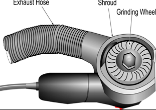 NIOSH - Workplace Solutions - Control of Hazardous Dust when Grinding Concrete Canopy, downdraft and side hoods are used to control dust
emissions from larger sources and when the dust particle velocity
is low to moderate. Hoods of this type can be used for larger
dust sources such as foundry shake-outs and bagging or barrel-filling
operations.
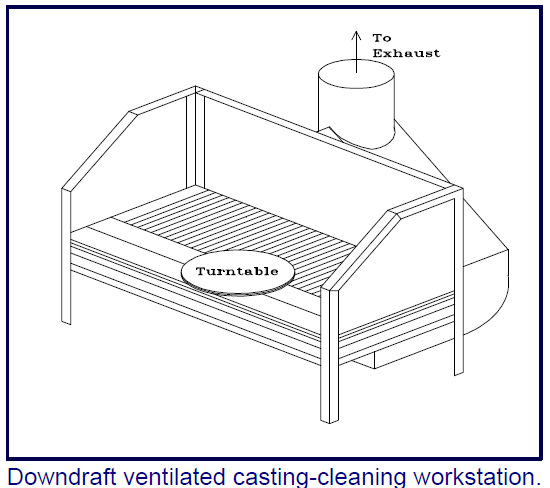 NIOSH Hazard Controls HC 23 - Controlling Silica Dust from Foundry Casting-Cleaning Operations.
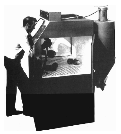
Enclosed hoods have an internal pressure differential that
maintains an inward flow of air through all openings in the
enclosure. These hoods enclose and isolate dust-producing
operations from the surrounding work area. They can be used
on conveyor systems, screening operations, belt conveyor transfer,
and other operations where worker intervention is minimal. 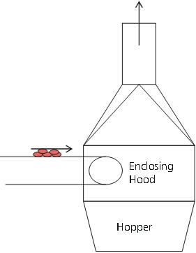 KEY DESIGN POINTS Capture Velocities
Effective local exhaust ventilation systems require adequate
volumetric flow rates and a hood design that generates adequate
capture velocity. In general, greater capture velocities are
required when dust particles need to be controlled. The following
table illustrates the relationship between the types of operations
and recommended capture velocities. RECOMMENDED CAPTURE VELOCITIES (ACGIH®- Industrial Ventilation - A Manual of Recommended Practice for Design - 28th Edition -© 2013)
Shape of the Exhaust Hoods (ACGIH®- Industrial Ventilation - A Manual of Recommended Practice for Design - 28th Edition -© 2013)
When air enters a hood opening, a certain amount of airflow
loss will occur. The amount of airflow reduction is referred
to as coefficient of entry (Ce). Ce = Actual Airflow Theoretical Airflow When the Ce is high, the hood is relatively efficient. Plain hoods are less efficient than flanged or tapered hoods.
Providing a flange around the perimeter of the hood opening
will improve hood capture efficiency. In some cases, a flange
can reduce exhaust airflow requirements by up to 25 percent.
TRANSPORT VELOCITY IN DUST-COLLECTION SYSTEMS
A typical dust-collection system requires air velocities in
the ductwork ranging from 3500 to 4000 feet per minute (fpm).
This velocity carries the dust-laden air collected from the
point of generation through the ductwork to a dust-collection
device such as a bag house. It is critical that the dust-laden
air is transported through the ductwork at a velocity which
does not allow the dust particles to settle out and deposit
in the duct.
The minimum duct velocity recommended in the ACGIH® Industrial Ventilation Manual - 28th edition, is 4000 - 4500 fpm for heavy dusts such as sand blasting dust and dust from foundry tumbling barrels and shake-out. For average dusts such as silica flour and general foundry dust, a minimum duct velocity of 3500 - 4000 fpm is recommended. As dust particles impinge on the inside of the ductwork at these velocities, erosion of the duct can occur. Minimizing transitions and elbows, or providing chip traps, can reduce the amount of dust impaction inside the duct. HOOD DESIGN EXAMPLES The following are examples of dust-collection hoods/systems for certain operations that may generate silica dust. Abrasive Blasting
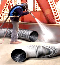  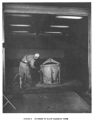 (Industrial Health & Safety Criteria for Abrasive Blast Cleaning Operations - National Institute for Occupational Safety and Health - HEW publication number (NIOSH) 75-122) Masonry Saw with Vacuum Dust Collection System 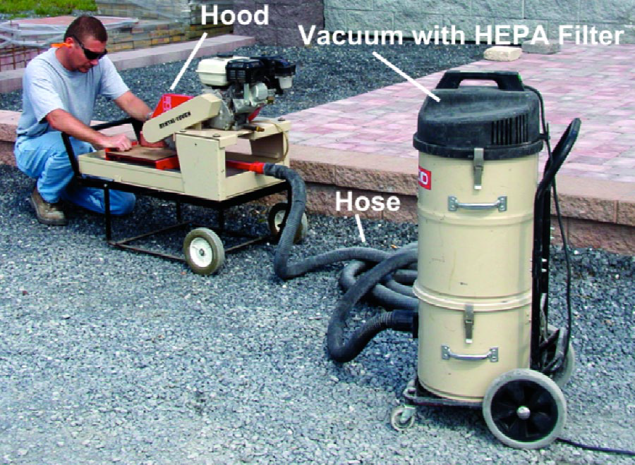 Employee
using a portable masonry saw with a vacuum dust collection system
(VDCS). VDCSs should include a dust collection device (hood),
vacuum, hose, and filter(s). Key points in using a VDCS include:
(OSHA® Fact Sheet - Controlling Silica Exposures in Construction While Operating Stationary Masonry Saws) Power Tools
Power tool use on silica-containing materials/stone such
as granite, concrete, masonry walls or floors can create an
airborne silica dust exposure. In addition to custom-made
hoods, electric and pneumatic power tools are
available with built-in shrouds and vacuum exhausts. The shroud
is connected to a flexible hose and HEPA vacuum cleaner or
other vacuum source. 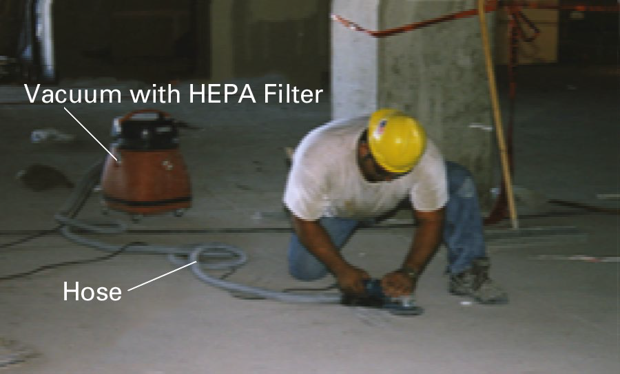 OSHA® Fact Sheet - Controlling Silica Exposures in Construction While Operating Hand-Operated Grinders Maintenance of Ventilation Systems
Dust control ventilation systems require periodic inspection,
testing and maintenance. Air flows at hood entries and duct
transport velocities should be measured periodically. The
dust collectors and fans also require regular, scheduled inspection
to ensure adequate air flow through the system. Often, an
exhaust system can appear to be functioning, when in fact
the air flow at the hoods is no longer meeting design requirements.
This means that dust control is reduced and employee exposure
to dust is increased. Cleaning silica dust from duct work, dust collectors and other parts of the system should not be done by dry sweeping. Use wet methods whenever possible, or HEPA filtered vacuuming. (Top) WET METHODS 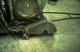 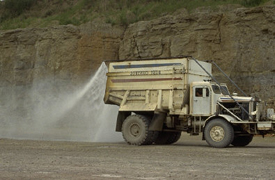
Concrete saw using water to control dust
Water truck keeps down dust on roads Wet methods involve the use of water or wetting agents to
reduce dust concentrations for some operations. Wet methods
are particularly effective when the water is introduced at
the point of dust generation so that the particles become
wetted before having a chance to disperse into the air. Where sand can be used wet, little or no dust is generated. In many sand and mineral-handling operations, a moisture content can be determined that substantially will reduce dust while not interfering with the process. Airborne dust can be captured through water sprays. This technique suppresses airborne dust by spraying fine droplets of water on the dust cloud. The water droplets and dust particles collide and form agglomerates. Once these agglomerates become too heavy to remain airborne, they settle from the air stream. However, limitations exist with the use of wet methods. Wet methods may be effective in reducing visible dust concentrations, but may not be effective in controlling respirable dust (silica) concentrations, which are invisible to the naked eye. The use of wet methods should be supplemented with other control measures, such as ventilation, whenever exposures cannot be controlled below the exposure limit. Wet Dust-Suppression Methods
The purpose of wet dust-suppression systems is to wet the
entire product or dust stream so that it generates less dust.
Effective wetting can be achieved by:
Static Spreading - The material is wetted while stationary. The diameter and contact angle of water droplets are important factors in static spreading. The surface coverage can be increased by reducing either the droplet diameter or its contact angle. Dynamic Spreading - The material is wetted while moving. The surface tension of the liquid, the droplet diameter, the material size and the droplet impact velocity are important variables in dynamic spreading. The surface coverage can be increased either by reducing the surface tension or by increasing the impact velocity. Factors affecting surface wetting Droplet Size - Surface wetting can be increased by reducing the droplet diameter and increasing the number of droplets. This can be achieved by reducing the surface tension and contact angle. Surface tension can be reduced by adding minute quantities of surfactants. This reduction in surface tension (or contact angle) results in reduced droplet diameter, an increase in the number of droplets and a decrease in the contact angle. Impact Velocity - Surface wetting can be increased by increasing the impact velocity. Impact velocity can be increased by increasing the system's operating pressure. A droplet normally travels through turbulent air before it impacts on the material surface. Due to the frictional drag of the turbulent air, the impact velocity of the droplet is less than its discharge velocity from the nozzle. Small droplets lose velocity faster than large ones. Therefore, to cover the greatest surface area, the best impact velocity for a given droplet diameter must be determined for each operation. Types of Wet Dust-Suppression Systems
Wet suppression systems include:
Plain Water Sprays - This method uses plain water to wet the material. However, most surfaces are difficult to wet with plain water due to its high surface tension. Water Sprays with Surfactant - This method uses surfactants to lower the surface tension of water. The droplets spread further and penetrate deeper into material piles. Foam - Water and a special blend of surfactant make the foam. The foam increases the surface area per unit volume, which increases wetting efficiency. Examples of Wet Methods The following are examples of wet methods, including limitations, where notable. Wet Drilling
Wet drilling has been used in mines and quarries to reduce
dust exposures. Whenever a choice is possible, wet drilling
should be selected over dry drilling. However, even when drilling
is wet, dust exposures still may exist since the dust, originally
dry, is not always wetted completely and retained. For certain
drill positions, such as overhead, the amount of water in
the drilling hole may not be sufficient and ventilation may
be needed. Also, whenever using wet methods, the evaporation
of the dust-laden water may constitute a secondary dust source
which must be considered and controlled.
Water Sprays
Water sprays cause the dust to form in heavier particles and
fall out of the air. In order to ensure good water contact,
water droplets should not be too large in relation to the
dust particles (usually not more than 100 times). For example,
water sprays are used:
The use of water sprays is not always effective in controlling
the very fine, "respirable" particles. Obtaining good contact
between dust particles and water droplets (unless the dust
is coarse) is difficult. Due to the movement of dusty material,
such as crushed rock on conveyor belts, dry areas may become
continuously exposed and dust may be liberated before becoming
wet. In such cases, continuous application of the water spray
as the material moves may help control the less fine dust.
The control of the respirable fraction of the dust is vital for silica exposures. Therefore, periodic air monitoring should be conducted even if the visual impression is that the water spray does suppress the dust. Wet Grinding and Cutting
Wet grinding and cutting should be chosen over dry operations.
These wet methods, commonly used to reduce dust exposures,
are not always effective in controlling dust that can escape
before becoming adequately wetted. Also, the dust-laden water
is thrown off as fine droplets which can evaporate before
falling to the floor, thus liberating dust. Water Cleaning The use of water is very important when cleaning up dusty
workplaces, especially as a substitute for dry sweeping and
when HEPA vacuum cleaning equipment is not available or feasible.
Water Application on Roadways
Watering roadways can be an effective dust suppression method
in mining, quarrying and construction operations. Dust created
by vehicles and heavy equipment operating over dirt surfaces
can result in significant exposure to silica. Environmental
conditions, extreme heat or cold, may affect the feasibility
and/or effectiveness of this dust-control method.
Wet Methods Considerations
When planning to use wet methods, consideration should include:
The use of water is encouraged and may be sufficient to solve
certain dust problems, but may not provide complete solutions.
The efficiency of wet methods depends on how completely the
particles can be wetted. Wetting agents, which improve the
spread of water over a surface, can be used. However, monitoring
of airborne dust is essential when using this method of control,
since the most difficult portion of dust to control by wet
methods is the "respirable" silica fraction - invisible to
the naked eye and most hazardous to health. © 2017 The Zurich Services Corporation. All rights reserved. | |||||||||||||||||||||||||||||||||||||||